Since the last 38 years, Bygging has been innovating and supplying ingenious products - tank jacking equipment or tank lifting equipment, submerged arc automatic girth welding machines and jacks for erecting grain storage silos. Bygging provides a spectrum of solutions based on the needs and requirements of storage tank construction companies worldwide with the sole purpose of making the process of constructing a storage tank safer, faster and cost effective for the tank builder.
Bygging provides a spectrum of solutions based on the needs and requirements of storage tank construction companies worldwide including countries such as Qatar, Netherlands, Poland, Romania, UAE, Oman,Saudi Arabia, Algeria, Indonesia, Brazil, Denmark, Singapore, South Africa, Malaysia, Nigeria, Ghana, Finland & many more
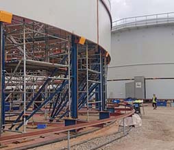
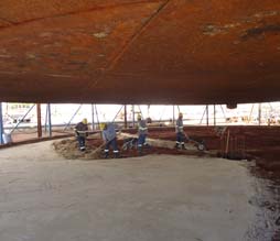
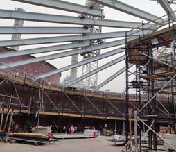
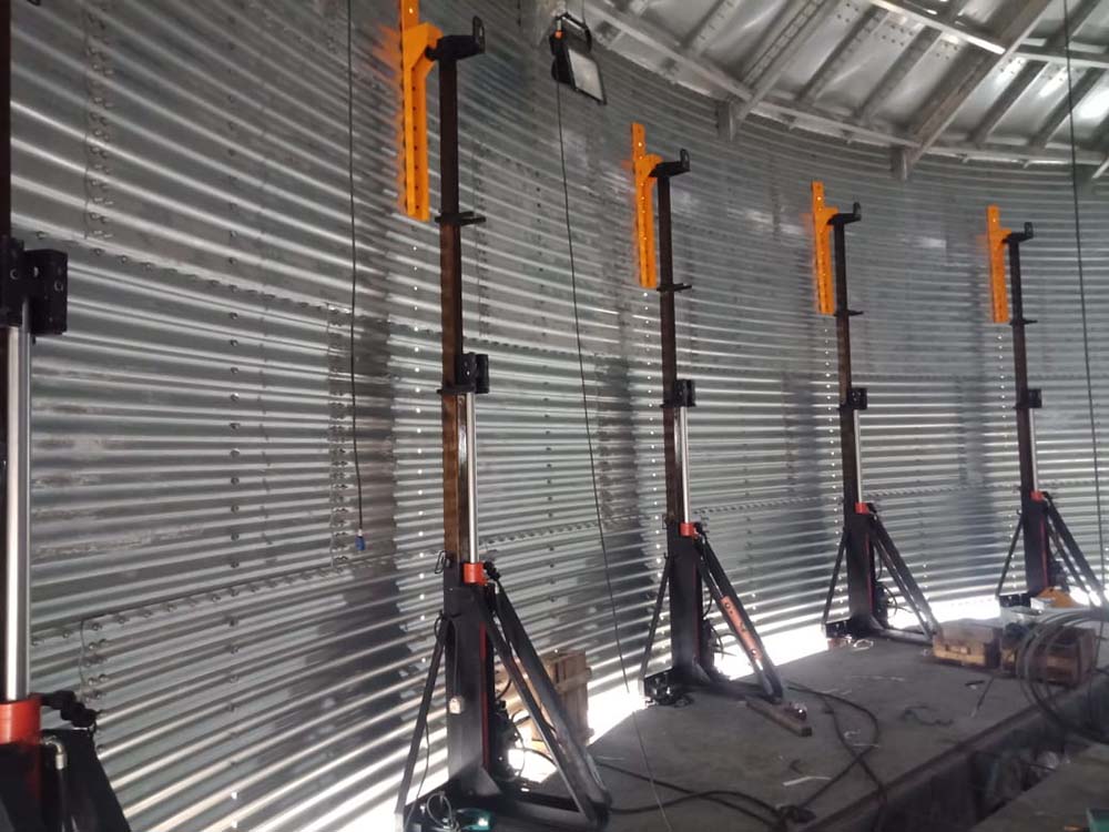
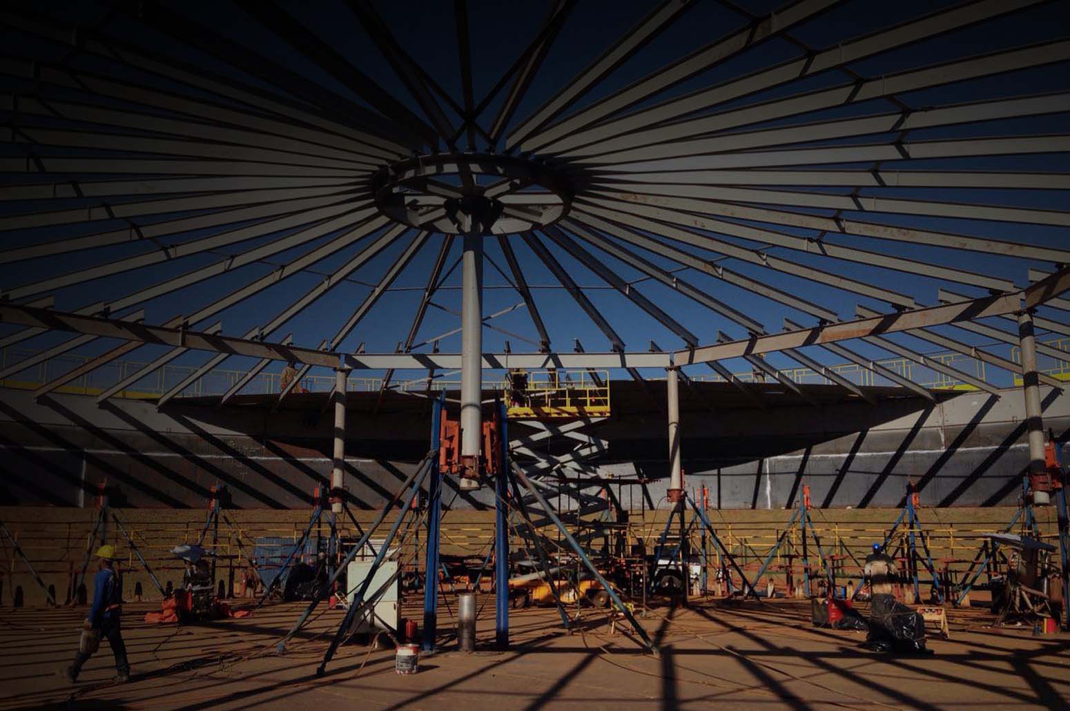
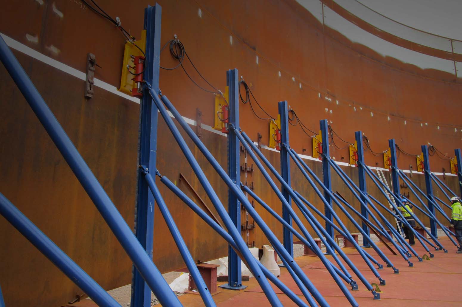
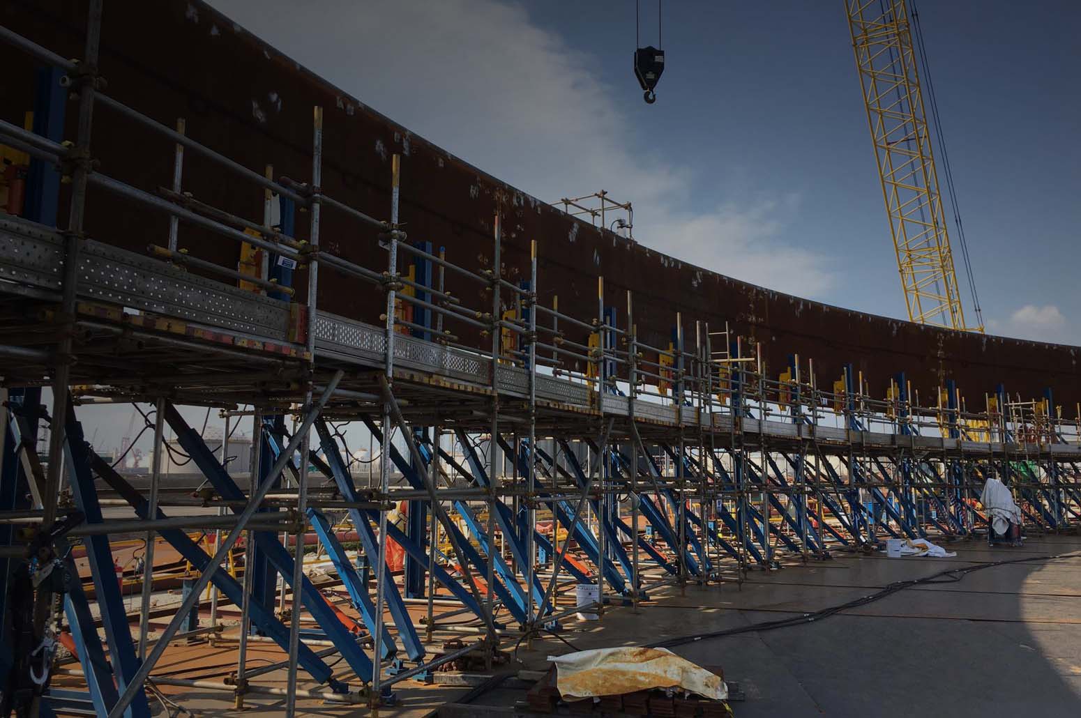
Bygging Jacking Equipment Is Used For

Experience
![]()
Countries
![]()
Projects
![]()